Contact Supplier

Mr. John chang
Leave a message| Payment Type: | L/C,T/T,Paypal |
|---|---|
| Incoterm: | FOB,CFR,CIF |
Basic Info
Model No.: YZPST-2SDW100
Brand: YZPST
Certification: CE
Encapsulation Structure: Plastic Sealed Transistor
Additional Info
Productivity: 1000
Transportation: Ocean,Air
Place of Origin: China
Supply Ability: 10000
Certificate: ISO9001-2008,ROHS
HS Code: 85413000
Port: Shanghai
Payment Type: L/C,T/T,Paypal
Incoterm: FOB,CFR,CIF
Product Description
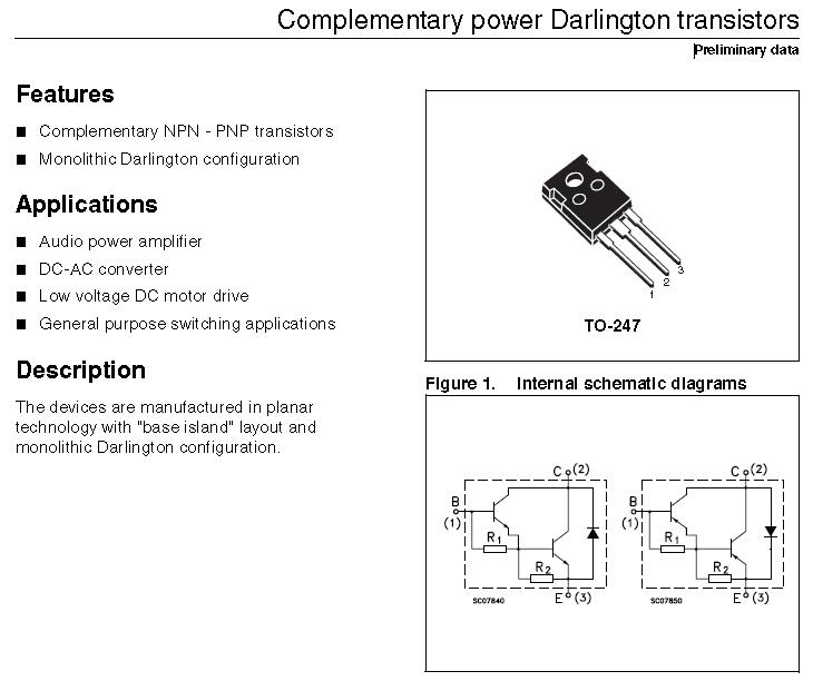
Complementary power Darlington transistors
YZPST-2SDW100
Features
■ Complementary NPN - PNP transistors
■ Monolithic Darlington configuration
Applications
■ Audio power amplifier
■ DC-AC converter
■ Low voltage DC motor drive
■ General purpose switching applications
Description
The devices are manufactured in planar technology with [base island" layout and monolithic Darlington configuration.
Table 1. Device summary
| Order code | Marking | Package | Packaging |
| 2SDW100 | 2SDW100 |
TO-247 |
Tube |
| 2SDW200 | 2SDW200 |
1 Absolute maximun ratings
Table 2. Absolute maximum ratings
|
Symbol |
Parameter | Value |
Unit | |
| NPN | 2SDW100 | |||
| PNP | 2SDW200 | |||
| VCBO | Collector-emitter voltage (IE = 0) | 80 | V | |
| VCEO | Collector-emitter voltage (IB = 0) | 80 | V | |
| IC | Collector current | 25 | A | |
| ICM | Collector peak current (tP < 5 ms) | 40 | A | |
| IB | Base current | 6 | A | |
| IBM | Base peak current (tP < 5 ms) | 10 | A | |
| PTOT | Total dissipation at Tc ≤ 25 °C | 130 | W | |
| TSTG | Storage temperature | -65 to 150 | °C | |
| TJ | Max. operating junction temperature | 150 | °C | |
Note: For PNP type voltage and current values are negative
Table 3. Thermal data
| Symbol | Parameter | Value | Unit |
| RthJC | Thermal resistance junction-case max | 0.96 | °C/W |
2 Electrical characteristics
Tcase = 25 °C; unless otherwise specified.
|
| Symbol | Parameter | Test conditions | Min. | Typ. | Max. | Unit |
|
ICBO | Collector cut-off current (IE = 0) |
VCE = 80 V |
|
|
0.5 |
mA |
|
ICEV | Collector cut-off current (VBE = - 0.3 V) |
VCE = 80 V |
|
|
0.1 |
mA |
|
ICEO | Collector cut-off current (IB = 0) |
VCE = 60 V |
|
|
0.5 |
mA |
|
IEBO | Emitter cut-off current (IC = 0) |
VEB = 5 V |
|
|
2 |
mA |
| VCEO(sus) (1) | Collector-emitter sustaining voltage (IB = 0) |
IC = 50 mA |
80 |
|
|
V |
|
VCE(sat)(1) |
Collector-emitter saturation voltage | IC = 5 A IB = 20 mA IC = 10 A IB = 40 mA IC = 20 A IB = 80 mA |
|
| 1.2 1.75 3.5 | V V V |
|
VBE(sat)(1) | Base-emitter saturation voltage |
C B |
|
|
3.3 |
V |
| (1) | Base-emitter voltage | I = 10 A V = 3 V | 1 |
| 3 | V |
|
hFE(1) |
DC current gain | IC = 5 A VCE = 3 V IC = 10 A VCE = 3 V IC = 20 A VCE = 3 V | 600 500 300 |
| 15000 12000 6000 |
|
| VF(1) | Diode forward voltage | IF = 10 A |
| TBD |
| V |
|
Is/b | Second breakdown current |
VCE = 25 V t = 500 ms |
|
TBD |
|
A |
1. Pulse test: pulse duration ≤ 300 µs, duty cycle ≤ 2 %.
For PNP type voltage and current values are negative.
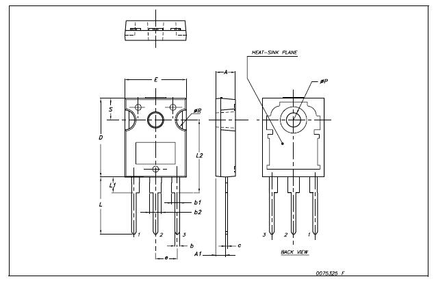
TO-247 Mechanical data
|
Dim. | mm. | ||
| Min. | Typ | Max. | |
| A | 4.85 |
| 5.15 |
| A1 | 2.20 |
| 2.60 |
| b | 1.0 |
| 1.40 |
| b1 | 2.0 |
| 2.40 |
| b2 | 3.0 |
| 3.40 |
| c | 0.40 |
| 0.80 |
| D | 19.85 |
| 20.15 |
| E | 15.45 |
| 15.75 |
| e |
| 5.45 |
|
| L | 14.20 |
| 14.80 |
| L1 | 3.70 |
| 4.30 |
| L2 |
| 18.50 |
|
| øP | 3.55 |
| 3.65 |
| øR | 4.50 |
| 5.50 |
| S |
| 5.50 |
|


Product Categories : Semiconductor Plastic Package > Silicon Transistor
Hot Products


Privacy statement: Your privacy is very important to Us. Our company promises not to disclose your personal information to any external company with out your explicit permission.

Fill in more information so that we can get in touch with you faster
Privacy statement: Your privacy is very important to Us. Our company promises not to disclose your personal information to any external company with out your explicit permission.