Communicate with Supplier? Supplier
John chang Mr. John chang
What can I do for you?
Chat Now Contact Supplier
YANGZHOU POSITIONING TECH CO., LTD.
Home> Blog> Thyristor (thyristor) schematic - Solutions - Huaqiang Electronic Network

Thyristor (thyristor) schematic - Solutions - Huaqiang Electronic Network

January 21, 2019

During the working process of the thyristor T, its anode A and cathode K are connected with the power source and the load to form a main circuit of the thyristor, and the gate G and the cathode K of the thyristor are connected with the device for controlling the thyristor. Control circuit for thyristors.
From the internal analysis of the thyristor work process:
The thyristor is a four-layer three-terminal device, which has three PN junctions J1, J2, and J3. The NP in the middle can be divided into two parts to form a composite tube of a PNP type triode and an NPN type triode.


When the thyristor is subjected to the forward anode voltage, in order for the thyristor to conduct copper, the PN junction J2 subjected to the reverse voltage must be prevented from blocking. The collector current of each transistor in Figure 2 is the base current of the other transistor. Therefore, when two mutually complex transistor circuits have sufficient gate current Ig flowing in, a strong positive feedback is formed, causing the two transistors to be saturated and the transistor is saturated.
Let the collector currents of PNP and NPN be corresponding to Ic1 and Ic2; the emitter currents should be Ia and Ik respectively; the current amplification factors should be a1=Ic1/Ia and a2=Ic2/Ik, set to reverse the J2 junction. The leakage current is Ic0,
The anode current of the thyristor is equal to the sum of the collector current and the leakage current of the two tubes:
Ia=Ic1+Ic2+Ic0 or Ia=a1Ia+a2Ik+Ic0
If the gate current is Ig, the thyristor cathode current is Ik=Ia+Ig
Therefore, it can be concluded that the thyristor anode current is: I=(Ic0+Iga2)/(1-(a1+a2))(1—1) type silicon PNP tube and silicon NPN tube corresponding to the current amplification factors a1 and a2 The abrupt change in its emitter current is shown in Figure 3.
When the thyristor is subjected to the forward anode voltage and the gate is not subjected to the voltage, in the formula (1-1), Ig=0, (a1+a2) is small, so the anode current Ia≈Ic0 of the thyristor The gatekeeper is in a positive blocking state. When the thyristor flows into the current Ig from the gate G at the forward anode voltage, since the sufficiently large Ig flows through the emitter junction of the NPN tube, the starting point amplification factor a2 is increased, and a sufficiently large pole electrode current Ic2 flows. The emitter junction of the PNP tube increases the current amplification factor a1 of the PNP tube, resulting in a larger pole electrode current Ic1 flowing through the emitter junction of the NPN tube. This strong positive feedback process proceeds quickly. From Fig. 3, when a1 and a2 increase with the emitter current and (a1+a2) ≈1, the denominator 1-(a1+a2) ≈0 in equation (1-1) increases the anode of the thyristor. Current Ia. At this point, the current flowing through the thyristor is completely determined by the voltage and loop resistance of the main circuit. The thyristor is already in a forward conduction state.
In the formula (1-1), after the thyristor is turned on, 1-(a1+a2)≈0, even if the gate current Ig=0, the thyristor can maintain the original anode current Ia and continue to conduct. through. After the thyristor is turned on, the gate has lost its effect.
After the thyristor is turned on, if the power supply voltage is continuously reduced or the loop resistance is increased to reduce the anode current Ia below the sustain current IH, since a1 and a1 decrease rapidly, when 1-(a1+a2)≈ At 0, the thyristor resumes the blocking state.
Contact Us

Author:

Mr. John chang

E-mail:

info@yzpst.com

Phone/WhatsApp:

8613805278321

Popular Products
You may also like
Related Information
Thyristor

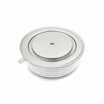
The full name thyratron, commonly known as thyristor, is a bistable power electronic device that contains 3 or more PN junctions that can switch from off-state to on-state or from on-state to...

Judgment of thyristor damage causes

When the thyristor damage need to check the analysis of the reasons, the core can be removed from the cooling jacket, open the core box and then remove the chip, observe the signs of damage to...

Radiator thermal resistance, thyristor dissipated power test method

A special sealing device is made by the method of disposing the dust in the radiator. This kind of device only leaves the fan through hole. Go to the construction site and construction site to...

Talking about the method of thyristor overcurrent protection

In order to prevent damage to the thyristor caused by the failure of the AC circuit inversion of the thyristor, the traditional method is to use a fast fuse for overcurrent protection. The advantage...

Related Categories

Email to this supplier

Subject:
Email:
Message:

Your message must be betwwen 20-8000 characters

Contact Us

Author:

Mr. John chang

E-mail:

info@yzpst.com

Phone/WhatsApp:

8613805278321

Popular Products
Blog News
Thyristor

August 14, 2023

Home

Product

Whatsapp

About Us

Inquiry

苏ICP备05018286号-1
We will contact you immediately

Fill in more information so that we can get in touch with you faster

Privacy statement: Your privacy is very important to Us. Our company promises not to disclose your personal information to any external company with out your explicit permission.

Send